
This circuit, enclosed in a small plastic box, can be placed into a bag or handbag. A small magnet is placed close to the reed switch and connected to the hand or the clothes of the person carrying the bag by means of a tiny cord. If the bag is snatched abruptly, the magnet looses its contact with the reed switch, SW1 opens, the circuit starts oscillating and the loudspeaker emits a loud alarm sound. A complementary transistor-pair is wired as a high efficiency oscillator, directly driving a small loudspeaker. Low part-count and 3V battery supply allow a very compact construction.
Circuit Diagram:
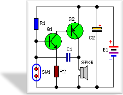
Mini Alarm Circuit Diagram
Parts:
Resistors
R1 = 330K
R2 = 100R
Capacitors
C1 = 10nF-63V
C2 = 100uF-25V
Semiconductors
Q1 = BC547
Q2 = BC327
Miscellaneous
B1 = 3V Battery or Two AA Cells in Series
SW1 = Read Switch & Small Magnet
SPKR = 8R Loudspeaker (See Notes)
Notes:
The loudspeaker can be any type; its dimensions are limited only by the box that will enclose it.
An on-off switch is unnecessary because the stand-by current drawing is less than 20µA.
Current consumption when the alarm is sounding is about 100mA.
If the circuit is used as anti-bag-snatching, SW1 can be replaced by a 3.5mm mono Jack socket and the magnet by a 3.5mm. Mono Jack plugs having its internal leads shorted. The Jack plug will be connected to the tiny cord etc.
Do not supply this circuit at voltages exceeding 4.5V: it will not work and Q2 could be damaged. In any case a 3V supply is the best compromise.
Reference >> http://www.circuit-lab.com/2009/10/mini-alarm-circuit-schematic.html
is this ckt working properly ???
ReplyDeletehow do you switch off the alarm?? do you just reset the magnet??
ReplyDelete